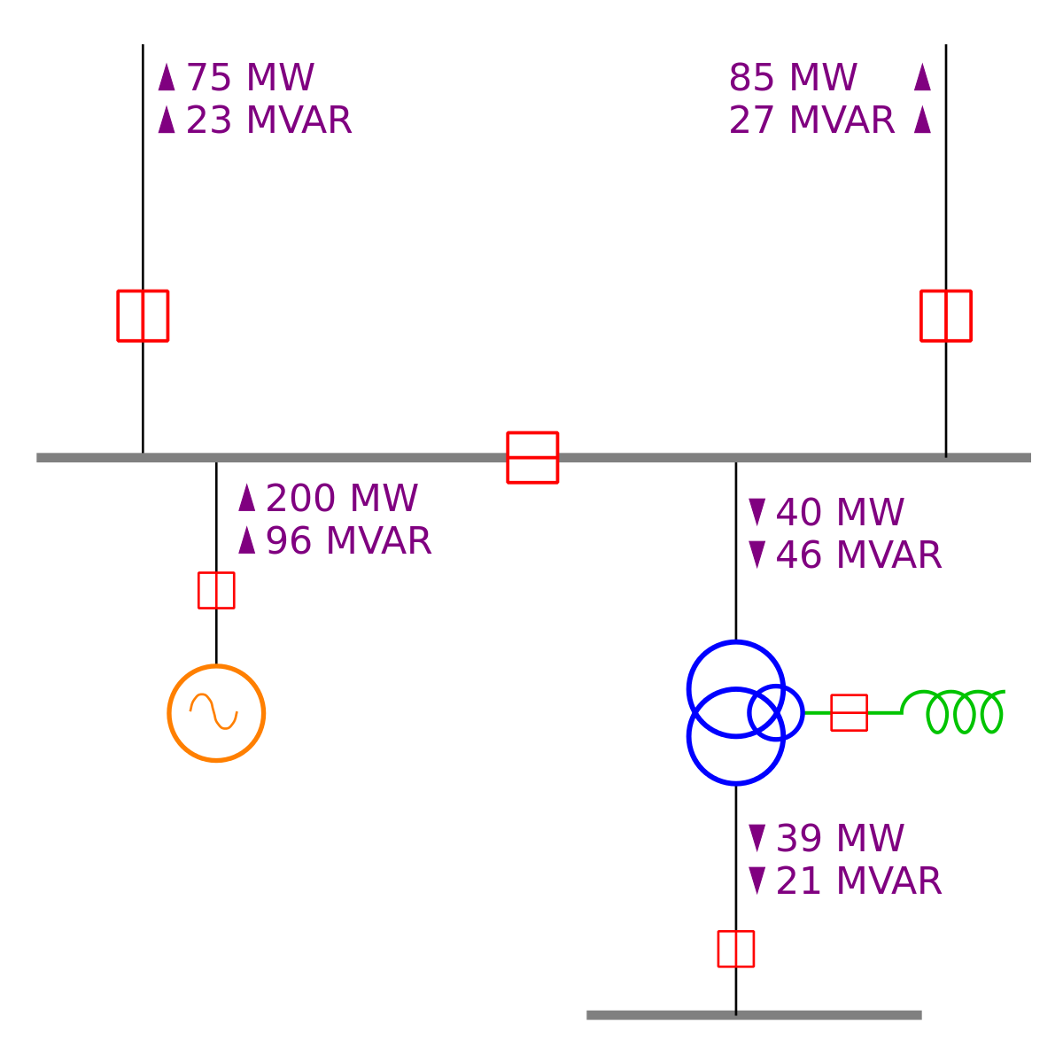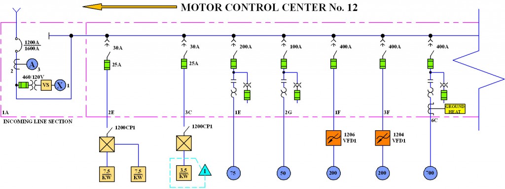

It shows a power-related system in a simple way.

It is a simplified drawing of the whole system or a portion. One-line Diagram or Single-line Diagram is a high-level schematic diagram developed for power engineering. This diagram is a form of schematic, which uses a single line to show. An electrical single line diagram abbreviated as SLD is also referred to as a one-line diagram. Single Line Diagram or One Line Diagram is for basic reference of management and engineers for planning and costing phase of any project. The next step following a block diagram, may be a single line diagram. The difference in Usage of SLD and 3LD in Project Life Cycle SLD is primarily used in panel schedule design, load schedule design, fault analysis design, protection system design whereas 3LD is used in control circuit diagrams, phase sequencing design, relay setting diagrams, meter & transformer connections etc. For the electrical single line diagram, a significant amount of information had to be considered when planning out the selection and placement of equipment. Difference in Applications of One Line Diagrams and Three Line Diagrams While SLD shows only one line for all electric wires 3LD used 3 or more lines to represent each and exact wires and where they are connected. Single line diagrams are electrical drawings that provide a basic visual guide to an electrical system detailing various nodes and interconnections which often serve as a base reference for further systems analysis.Ī three-line diagram is, however, a more detailed presentation of an electric system with actual cabling information involving positive, negative, ground cables for DC, L1, L2, 元, Neutral and Ground cables on an AC system.


 0 kommentar(er)
